
User Manual

Publication 1398-5.0 – October 1998
6-20 Interfaces
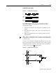
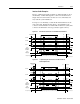
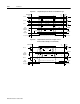
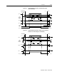
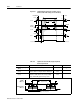
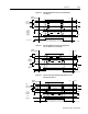
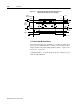
The input circuits shown in the following diagrams support
connections to differential TTL line drivers, single-ended TTL line
drivers and open collector devices. These inputs are selectable under
software control.
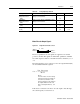
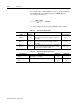
Table 6.19: Auxiliary Encoder/Step and Diection/CW & CCW
(Step Up & Down) Signals
Auxiliary Encoder Input Pin
Number
Description Internal
Connections
AX + and AX-, or
Step + and Step-, or
CW+ (Step Up+) and
CW- (Step Up-)
J1-14 (+)
J1-15 (-)
Auxiliary Channels A(+) and A(-). Differ-
ential, quadrature, or TTL level encoder
input. The signal input and resolution are
selectable. (Refer to ULTRA Master –
Drive Setup.)
J3-14 (+)
J3-15 (-)
BX (+) and BX(-), or
DIR (+) and DIR(-), or
CCW+ (Step Down+) and
CCW- (Step Down-)
J1-16 (+)
J1-17 (-)
Auxiliary Channels B(+) and B(-). Differ-
ential, quadrature, or TTL level encoder
inputs. The signal input and resolution are
selectable. (Refer to ULTRA Master –
Drive Setup.)
J3-16 (+)
J3-17 (-)
IX (+) and IX (-) J1-18 (+)
J1-19 (-)
Auxiliary Input Channels I(+) and I(-). Dif-
ferential, quadrature, or TTL level
encoder inputs.
J3-18 (+)
J3-19 (-)
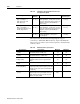
Table 6.20: Quadrature Interface Specifications
Specification Description Minimum Maximum
ON State Voltage
(Volts)
Voltage difference between the + and –
inputs that indicate an ON state. 1.0 +15
OFF State Voltage
(Volts)
Voltage difference between the + and –
inputs that indicates an OFF state. -1.0 -15
Common Mode
Voltage (Volts)
Voltage difference between an encoder sig-
nal input and the reference ground of the
drive.
-15 +15
Current Draw
(mA)
Current draw into the + input or – input
-5 +5
A or B Signal
Frequency (MHz)
Frequency of the A or B line inputs. Count
frequency is 4 times this frequency, since the
circuitry counts each of the four transitions in
a single line.
1
Index Pulse Width
(nsec)
Pulse width of the index signal. The index
signal is active for a percentage of the revo-
lution, therefore the speed of the encoder
dictates the pulse width.
500