
User Manual

Publication 1398-5.0 – October 1998
6-18 Interfaces
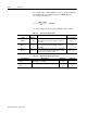
For example, a motor with a 2000 line encoder is rotating at 3000 rpm,
and the Motor Encoder Output signal is set to
Divide by 1, the
encoder signal frequency is:
A counter counting all edges registers 400 kHz for this example.
f
out
3000 2000⋅
60 1⋅
---------------------------- 100kHz==
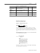
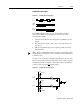
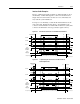
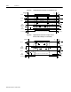
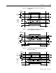
Table 6.17: Motor Encoder Output Signal
Encoder
Output
Pin
Number
Description Internal
Connections
AOUT (+)
AOUT (-)
J1-7 (+)
J1-8 (-)
Motor Output Channels A(+) and A(-). Differential
TTL levels from line driver. Signal resolution is
selectable.
J3-7 (+)
J3-8 (-)
BOUT (+)
BOUT (-)
J1-9 (+)
J1-10 (-)
Motor Output Channels B(+) and B(-). Differential
TTL levels from line driver. Signal resolution is
selectable.
J3-9 (+)
J3-10 (-)
IOUT (+)
IOUT (-)
J1-11 (+)
J1-12 (-)
Motor Output Channels I(+) and I(-). Differential
TTL levels from line driver. Output pulse occurs
once per motor shaft revolution.
J3-11 (+)
J3-12 (-)
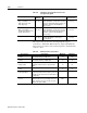
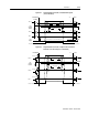
Table 6.18: Motor Encoder Output Specifications
Specification Description Minimum Maximum
Differential Output
(Volts)
Voltage measured between the (+) and (-)
pins with R
L
= 100 Ohm. 2.0
Output Current
(mA)
Current flowing out of the (+) or (-) pin.
-20 +20