
User Manual


Publication 1398-5.0 – October 1998
6-16 Interfaces
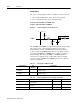
Analog Outputs
Two selectable outputs are available for monitoring by the user:
ANALOG 1 (J1-30) and ANALOG 2 (J1-31). A 12 bit digital to
analog converter (DAC) generates ANALOG 1. ANALOG 2 is a
filtered PWM signal with 8 bit resolution and a carrier frequency of
32.8 kHz. Both outputs are scaled to a range of -10 to +10 Volts.
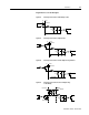
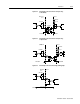
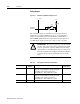
Figure 6.19 ANALOG 1 and ANALOG 2 Output Circuits
Intro
DriveJ1
-5 Volts
10K
100
-
+
20K
ANALOG
OUTPUT
!
Intro
ATTENTION: The user may need to provide an external
circuit to delay output of the analog signal when the signal
is used to perform an operation. After reset both analog
outputs may be in an indeterminate state for a short period
before they stabilize at the setting stored in memory. Failure
to observe this precaution could result in severe bodily
injury.
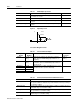
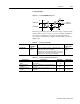
Table 6.15: Analog Outputs: ANALOG 1 and ANALOG 2
Analog Output Pin
Number
Description Internal
Connections
ANALOG 1 J1-30 Selectable analog output with 12 bit resolution. Dis-
plays the selected firmware variable along with
selectable scale and offset (refer to the
ULTRA Master – I/O Configuration section).
A1
ANALOG 2 J1-31 Selectable analog output with 8 bit resolution. Dis-
plays the selected firmware variable along with
selectable scale and offset (refer to the
ULTRA Master – I/O Configuration section).
A2
ACOM J1-28 Analog Common (return). COM