
User Manual


Publication 1398-5.0 – October 1998
Interfaces 6-15
Command Input
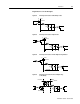
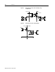
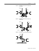
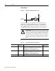
The analog command signal to the drive has a range of ±10 Volts. The
signal is either a torque, velocity or position command, depending on
the software configuration of the drive. The differential input is
processed by a 16 bit analog to digital converter (ADC) to produce a
digital value.
Figure 6.18 Analog COMMAND Input Circuit
Intro
DriveJ1
COMMAND+
COMMAND-
10K
20K
10K
10K
10K
ANALOG
+
-
COMMAND
20K
20K
.01uF
.01uF
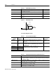
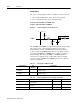
Table 6.13: Analog Command Input
Analog Input Pin
Number
Description Internal
Connections
COMMAND J1-22 (+)
J1-23 (+)
Analog command signal is a differential type sig-
nal to drive the servo controller.
Separate scale and offset parameters are used
for the input, depending on whether the signal is
a position, velocity or torque command.
J3-22 (+)
J3-23 (-)
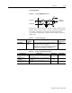
Table 6.14: Analog Command Input Specifications
Specification Description Minimum Maximum
Resolution
(Bits)
Number of units that the input voltage is
converted to. 16
Input Impedance
(kOhms)
Open circuit impedance measured between
(+) and (-). 13.3
Input Signal Range
(Volts)
Allowable voltage applied between (+) and
(-) inputs. 0 ±10