
User Manual


Publication 1398-5.0 – October 1998
Interfaces 6-11
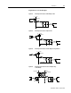
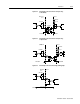
Output Interface Circuit Examples
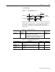
Current Limit An active state indicates the torque current is limited.
Up To Speed An active state indicates the velocity loop AT SPEED signal is active. The at
speed level is a selectable setting.
Drive Enabled An active state indicates the ENABLE signal is active and no fault is detected.
Bus Charged An active state indicates the DC bus is energized.
Disabling Fault An active state indicates a fault disabled the drive.
In Motion An active state indicates the indexing sequence is in the motion portion.
In Dwell An active state indicates the indexing sequence is in the dwell portion.
Sequence Complete An active state indicates all batches of the indexing sequence are finished.
Registered An active state indicates the indexing move has been adjusted after sensing
the registration sensor.
At Home An active state indicates the drive is at the home position.
Axis Homed An active state indicates the drive has been homed.
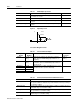
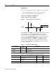
Table 6.10: Transistor Output Specifications
Parameter Description Minimum Maximum
ON state Voltage Voltage difference between the +24 VDC
supply and the output when the transistor is
ON.
0 VDC 1.5 VDC
ON state current Current flow when the transistor is ON. 0 mA 50 mA
OFF state Voltage Voltage difference between the +24 VDC
supply and the output when the transistor is
OFF.
0 Volts 50 Volts
OFF state current Leakage current from the output when the
transistor is OFF.
-0.1 mA 0.1 mA
Table 6.9: OUTPUT1, OUTPUT2, OUTPUT3 and OUTPUT4 Functions (continued)
Function Description
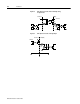
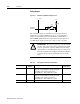
Figure 6.10 Drive Output Connected to an Opto-Isolator
Intro
DriveJ1
+24VDC
Pin 13
Pin 6
24VCOM
1K