
User Manual


Publication 1398-5.0 – October 1998
6-10 Interfaces
Selectable Output Circuits
Table 6.7: BRAKE Output Specifications
Parameter Description Maximum
ON state resistance Internal resistance between J1-49 (+) and J1-50 (-) when
the contacts are closed.
1 Ohm
ON state current Current flow through the relay when contacts are closed. 1 A
OFF state current Leakage current from either output when the relay contacts
are open.
0.01 mA
OFF state Voltage Voltage difference between the outputs with open relay
contacts.
50 Volts
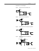
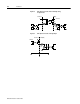
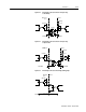
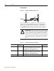
Figure 6.9 Digital Output Circuit
Intro
J1 Drive
+24VDC
Table 6.8: General and Dedicated Outputs
Digital
Output
Pin
Number
Function/Description Internal Con-
nections
READY J1-24 (+) J1-
25 (-)
Relay closure indicates the drive does
not
have a
fault. (Refer to “READY Output Specifications” on
page 6-9)
J3-24 (+)
J3-25 (-)
BRAKE J1-49 (+) J1-
50 (-)
Relay closure releases the brake. Delay time is
selectable. (Refer to “BRAKE Output Specifications”
on page 6-10)
OUTPUT 1 J1-42 General purpose output. Selectable from one of sev-
eral drive functions. (Refer to Table 6.9)
OUTPUT 2 J1-43
OUTPUT 3 J1-44
OUTPUT 4 J1-45
Table 6.9: OUTPUT1, OUTPUT2, OUTPUT3 and OUTPUT4 Functions
Function Description
In Position An active state indicates the position window condition is satisfied, and the
zero speed condition is satisfied. The position window and zero speed range
are selectable settings.
Within Window An active state indicates the position window condition is satisfied. The posi-
tion window range is a selectable setting.
Zero Speed An active state indicates the velocity loop zero speed signal is active. The
zero speed limit is a selectable setting.
Speed Window An active state indicates the velocity loop speed window is active. The speed
window range is a selectable setting.