
User Manual


Publication 1398-5.0 – October 1998
Interfaces 6-9
Digital Outputs
Two types of discrete output circuits are available on the J1 connector:
● Dedicated relay outputs
● Selectable transistor based outputs
Both types support 24 VDC logic interfaces:
Dedicated Relay Outputs
BRAKE and DRIVE READY. Each output is a normally open relay.
The brake contacts are rated for 1 Amp at 50 Volts. The Drive Ready
contacts are rated for 100 mA at 50 Volts.
If an option, such as 90V brake, requires more power, a user provided
relay may be driven by these outputs up to the specified levels.
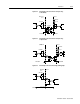
Selectable Transistor Outputs
OUTPUT 1, OUTPUT 2, OUTPUT 3, and OUTPUT 4 are 24 VDC,
optically isolated, active high, current sourcing, single ended
transistor output channels. Each channel sources a maximum of 50
mA.
Ready and Brake Circuits
The specifications for these outputs are as follows:
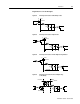
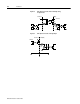
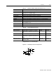
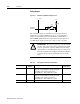
Figure 6.8 READY and BRAKE Circuits
Intro
J1 Drive
+
-
Normally
Open
Relay
Table 6.6: READY Output Specifications
Parameter Description Maximum
ON state resistance Internal resistance between J1-24 (+) and J1-25 (-) when
the contacts are closed.
1 Ohm
ON state current Current flow through the relay when contacts are closed. 100 mA
OFF state current Leakage current from either output when the relay contacts
are open.
0.01 mA
OFF state Voltage Voltage difference between the outputs with open relay
contacts.
50 Volts