
User Manual


Publication 1398-5.0 – October 1998
6-4 Interfaces
Digital Inputs
ULTRA 200 Series drives have active high, current sinking inputs,
which prevent disconnects and ground faults from activating a drive.
Two discrete input circuits types are available on the J1 connector.
Both circuits support logic type interfaces with 24 Volt, optically
isolated, single ended and active high, current sinking characteristics.
Dedicated Control Circuits
The ENABLE input interfaces with switch closures or sourcing type
outputs. The input channel sinks 4.5 mA nominal.
Selectable Circuits
INPUT 1, INPUT 2, INPUT 3, INPUT 4 and FAULT RESET operate
with switch closures or sourcing type circuitry. Each input channel
sinks 4.5 mA nominal. Selectable inputs are:
● Drive Mode Select
● Integrator Inhibit
● Follower Enable
● Forward Enable
● Reverse Enable
● Preset Select A
● Preset Select B
● Preset Select C
● Operation Mode Override
● Start Index
● Define Home
● Start Homing
● Remove COMMAND Offset
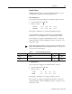
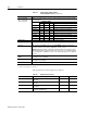
Table 6.2: 5 Volt Power Supply Specifications
Parameter Description Minimum Maximum
Output Voltage
(VDC)
Voltage between +5VDC and +5VCOM
4.75
5.25
Output Current
(mA)
Current flow
0250
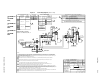
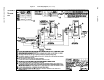
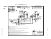
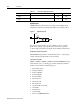
Figure 6.1 Digital Input Circuit
Intro
DriveJ1
5K
1K
24VCOM