
User Manual


Publication 1398-5.0 – October 1998
6-2 Interfaces
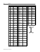
Pin Signal Description Pin Signal Description Pin Signal Description
1 +5VDC Encoder +5V
DC
21 RESET Fault Reset 41 Reserved
2 ECOM Encoder
Common
22 COMMAND+ Analog
Command+
42 OUTPUT1 Selectable
Output 1
3 +5VDC Encoder
+5V DC
23 COMMAND- Analog
Command-
43 OUTPUT2 Selectable
Output 2
4 ECOM Encoder
Common
24 READY+ Drive Ready+ 44 OUTPUT3 Selectable
Output 3
5 +24VDC Isolated
+24 VDC
25 READY- Drive Ready- 45 OUTPUT4 Selectable
Output 4
6 24VCOM Isolated 24V
Common
26 +24VDC Isolated
+24 VDC
46 Reserved
7 AOUT+ Motor Encoder
Output
Channel A+
27 +I LIMIT Positive
Current Limit
47 Reserved
8 AOUT- Motor Encoder
Output
Channel A-
28 ACOM Analog
Common
48 Reserved
9 BOUT+ Motor Encoder
Output
Channel B+
29 -I LIMIT Negative
Current Limit
49 BRAKE+ Brake
Enable+
10 BOUT- Motor Encoder
Output
Channel B-
30 ANALOG1 Analog
Output 1
50 BRAKE- Brake
Enable-
11 IOUT+ Motor Encoder
Output
Channel I+
31 ANALOG2 Analog
Output 2
12 IOUT- Motor Encoder
Output
Channel I-
32 INPUT1 Selectable
Input 1
13 24VCOM Isolated 24V
Common
33 INPUT2 Selectable
Input 2
14 AX+ Auxiliary
Encoder
Channel A+
34 INPUT3 Selectable
Input 3
15 AX- Auxiliary
Encoder
Channel A-
35 INPUT4 Selectable
Input 4
16 BX+ Auxiliary
Encoder
Channel B+
36 Reserved
17 BX- Auxiliary
Encoder
Channel B-
37 Reserved
18 IX+ Auxiliary
Encoder
Channel I+
38 Reserved
19 IX- Auxiliary
Encoder
Channel I-
39 Reserved
20 ENABLE Drive Enable 40 Reserved
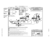
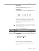
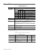
pin 25
pin 26
pin 50
pin 1