
User Manual


Publication 1398-5.0 – October 1998
4-4 Unpacking, Inspecting and Storing
Drive Checkout Test
This test sequentially verifies that:
● Drive power wiring is correct and start-up logic is functioning
● The drive and motor are correctly wired
● Drive serial communications are operational
Before beginning “Initial Power-up”, please check the following:
● All wiring and mounting to verify correct installation
● Input voltages to ensure they do not exceed specifications for the
drive or motor.
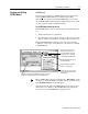
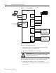
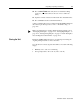
Figure 4.1 Connection Diagram
Intro
J4
DRIVE
J1
TB1
TB1
26 +24V
20 ENABLE
21 FAULT RESET
2 RCV
3 XMT
5 COM
Phase R 1
Phase S 2
Phase T 3
Motor Gnd 4
L1 7
L2/N 8
Gnd 9/10
100-240 VAC
50/60 Hz
Single Phase
XMT
RCV
COM
Close to ENABLE drive
Close to RESET faults
Power Source
TB1
L1 7
L2/N 8
Gnd 10
L3 9
or
J2
Motor
Encoder
100-240 VAC
50/60 Hz
Three Phase
Power Source
Gnd = Pin 9 for DDM-010, DDM-020, DDM-030
Gnd = Pin 10 for DDM-075 using single phase
!
Intro
ATTENTION: Be prepared to disable the drive or remove
input power if excessive motor motion occurs while per-
forming the following steps.