
User Manual


Publication 1398-5.0 – October 1998
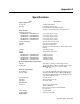
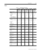
G-2 Specifications
Selectable (5) 24 Volt, Optically Isolated, Single ended, Active High,
Current Sinking, 4.5 mA nominal
ENABLE 24 Volt, Optically Isolated, Single ended, Active High,
Current Sinking, 4.5 mA nominal
Digital Outputs
Selectable (4) 24 Volt, Optically Isolated, Single-ended, Active High,
Current Sourcing, 50 mA maximum
BRAKE 24 Volt, Normally Open Relay, 1 A
READY 24 Volt, Normally Open Relay, 100 mA
Digital I/O Power Supply Isolated 24V @ 250 mA, fused
Analog Inputs
Positive Current Limit
(+I LIMIT)
0 to 10 Volt, 10-bit, single-ended, 5 kOhm input Imped-
ance
Negative Current Limit
(-I LIMIT)
0 to 10 Volt, 10-bit, single-ended, 5 kOhm input Imped-
ance
COMMAND ±10 Volt, Differential, 16-bit, 13 kOhm input Impedance,
offset software adjustable
Analog Outputs
ANALOG1 0 to 10 Volt, 12-bit, 2 mA maximum
ANALOG2 0 to 10 Volt, 8-bit, 2 mA maximum
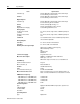
Auxiliary Encoder Signal Input
26LS33 Input, 4 MHz Count Frequency
Differential/Single-ended
A/B
Step/Direction
CW/CCW
5 Volt Power Supply 5V @ 250 mA, fused
Motor Encoder Output AM26C31 or AM26LS31 Differential Driver;
Divide by 1, 2, 4, or 8
Differential output is 2.0 Vdc across a 100 Ohm load
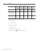
CPU/Memory
Parameter Data Retention 20 years
Microcontrollers (2) Motorola 68HC16
EPROM 128 kB Flash Memory
RAM 34 kB
User Parameter Memory (2) 512 kB Serial EEPROM
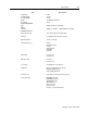
Motor Overload Protection Motor overload protection operates within 8 minutes at
200% overload, and within 20 seconds at 600% overload.
PWM Carrier Frequency
1398-DDM-010 or 1398-DDM-010X,
1398-DDM-020 or 1398-DDM-020X,
1398-DDM-050 or 1398-DDM-050X,
1398-DDM-075 or 1398-DDM-075X,
1398-DDM-150 or 1398-DDM-150X
10 kHz/5 kHz
10 kHz/5 kHz
10 kHz/5 kHz
10 kHz/5 kHz
5 kHz
Current Regulation
Type Digital, PI with Back-EMF compensation, Synchronous
-3dB Bandwidth 1.2 kHz
-45° Bandwidth 600 Hz
Resolution 10-bit
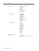
Speed Regulation
Type Digital, PID
Item Specification