
User Manual


Publication 1398-5.0 – October 1998
C-2 TouchPad Instructions
5. After self-test is completed, the TouchPad display defaults to the
branch title
DRVSETUP.
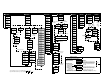
6. Horizontal and vertical movement through the TouchPad Com-
mand Tree and parameter modification is explained below. The
“TouchPad Command Tree (sheet 1 of 2)” on page C-4 illus-
trates the structure.
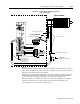
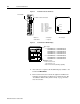
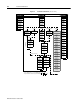
Figure C.1 TouchPad Connection and Pinouts
Intro
1. Insert tab
2. Mate serial connectors
Pin 9
Pin 6
Pin 1
Pin 5
Pin 1
Pin 2
Pin 3
Pin 4
Pin 5
Pin 6
Pin 7
Pin 8
Pin 9
Receive +
Not used
Not used
Transmit +
+5VDC Common
TouchPad Sense
Receive -
Transmit -
+5VDC
• Address 0 • 8 Data bits • No Parity bit
• 19200 Baud • 1 Stop bit
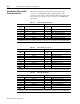
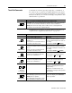
Figure C.2 TouchPad Version Number Display
Intro
Ver11.10
Drive Type:
1 = 1398-DDM-010 or 1398-DDM-010X,
1398-DDM-020 or 1398-DDM-020X,
1398-DDM-030 or 1398-DDM-030X,
1398-DDM-075 or 1398-DDM-075X,
1398-DDM-150 or 1398-DDM-150X
2 = 1398-DDM-005 or 1398-DDM-005X,
1398-DDM-009 or 1398-DDM-009X,
1398-DDM-019 or 1398-DDM-019X
Firmware Level:
1.00 = Version 1.00
1.10 =Version 1.10
2.00 = Version 2.00 (Indexing capable)