
User Manual
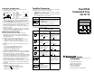

Publication 1398-5.0 – October 1998
B-30 Cable Diagrams, Schematics and Examples
Allen-Bradley 9/Series CNC
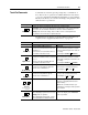
Family Connections
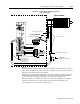
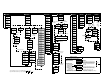
The tables below list the connections necessary between the
connectors on Allen-Bradley 9/Series CNC Controllers. The
controller may be wired to either a Breakout Board connection from
the J2 connector or directly to the J1 connector on a ULTRA 200
Series drive.
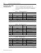
Table B.1: 9/260 or 9/290 to Breakout Board
9/260 or 9/290 8520-ASM-3 Drive Connections
J1, J2, J3
Pin
Signal J2
Pin
Signal
3 CHA_HI 7 MtrEncdr Input Chnl A+
4 CHB_HI 9 MtrEncdr Input Chnl B+
5 CHZ_HI 11 MtrEncdr Input Chnl Index+
12 CHA_LO 8 MtrEncdr Input Chnl A-
13 CHB_LO 10 MtrEncdr Input Chnl B-
14 CHZ_LO 12 MtrEncdr Input Chnl Index-
NOTE:
A-B 845 encoders are usually wired with the A- signal into the A+ signal on the Allen-Bradley drive
Table B.2: 9/260 or 9/290 to J1 Connector
9/260 or 9/290 8520-ASM-3 Drive Connections
J1, J2, J3
Pin
Signal J1
Pin
Signal
3 CHA_HI 7 Mtr Output Chnl A+
4 CHB_HI 9 Mtr Output Chnl B+
5 CHZ_HI 11 Mtr Output Chnl Index+
12 CHA_LO 8 Mtr Output Chnl A-
13 CHB_LO 10 Mtr Output Chnl B-
14 CHZ_LO 12 Mtr Output Chnl Index-
9 DRIVE 22 Analog Cmd+
18 DRIVE.RET 23 Analog Cmd-
NOTE:
A-B 845 encoders are usually wired with the A- signal into the A+ signal on the Allen-Bradley drive
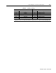
Table B.3: 9/230 to Breakout Board
9/230 8520-ASM-4 Drive Connections
Pin Signal J2 Pin Signal
11 CHA_HI 7 MtrEncdr Input Chnl A+
10 CHB_HI 9 MtrEncdr Input Chnl B+
39 CHZ_HI 11 MtrEncdr Input Chnl Index+
41 CHA_LO 8 MtrEncdr Input Chnl A-
40 CHB_LO 10 MtrEncdr Input Chnl B-
9 CHZ_LO 12 MtrEncdr Input Chnl Index-
NOTE:
A-B 845 encoders are usually wired with the A- signal into the A+ signal on the Allen-Bradley drive