
User Manual

Publication 1398-5.0 – October 1998
Appendix B
Cable Diagrams, Schematics and
Examples Appendix B
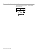
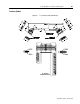
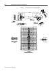
Factory supplied cables allow ULTRA 200 Series drives to conform to
the European Union Directives when connecting the drive to motors,
controllers or computers. The following diagrams provide information
on the cables available from the factory.
Refer to Appendix A, “Options and Accessories” for ordering
information.
The information below applies to all factory supplied cables.
● Wire Insulation Type: Polyvinyl Chloride
● Conductor size: 0.08 mm
2
(28 AWG) tinned copper, except as
noted below.
[0.25 mm
2
(24 AWG) on 9101-1372, 9101-1374 and 9101-1379]
[1.5 mm
2
(16 AWG) on 9101-1190, 9101-1381, 9101-1385 and
9101-1467]
[2.5 mm
2
(14 AWG) on 9101-1191 and 9101-1382]
[6 mm
2
(10 AWG) on 9101-1192 and 9101-1383]
[10 mm
2
(8 AWG) on 9101-1384 and 9101-1399]
[16 mm
2
(6 AWG) on 9101-1193]
● Braid Shield Coverage: 85% minimum
● Jacket Material: Thermoplastic elastomer
● Moldings: 105°C (221°F) Black PVC
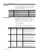
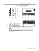
● Minimum Bend Radius
● Cables are manufactured to inch dimensions. Millimeter
dimensions are approximate conversions from inches.
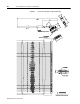
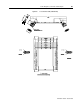
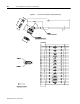
Feedback and Control Cables Motor Power Cables
Connector mm (in.) Cable mm (in.)
Controller (J1) 171.45 (6.75) 9101-1190 76.2 (3)
Encoder (J2) 129.54 (5.10) 9101-1191 76.2 (3)
9101-1192 120.65 (4.75)
9101-1193 177.8 (7)
9101-1381 76.2 (3)
9101-1382 76.2 (3)
9101-1383 120.65 (4.75)
9101-1384 152.4 (6)
9101-1385 88.9 (3.5)
9101-1399 152.4 (6)
9101-1467 76.2 (3)