
User Manual

Publication 1398-5.0 – October 1998
11-6 Maintenance and Troubleshooting
Troubleshooting Two front panel indicators display the status of the drive on a
continuous basis:
● The Status display indicates the operating mode of the drive (A, F,
P, etc.).
● The DC Bus LED lights whenever the main AC input is
connected to line voltage.
A table of problems, potential causes, and appropriate actions to take
to resolve the problem is included below.
Error Codes
If problems persist after attempting to carefully troubleshoot the
system, please contact your local distributor for further assistance.
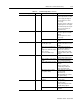
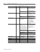
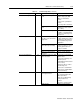
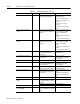
Table 11.1: Troubleshooting Guide
Problem or Symptom Error Code Possible Cause(s) Action/Solution
Status display not lit. No AC power Verify power (115/230VAC
single phase or 230 VAC
three phase) is applied to
the drive.
Blown power fuse(s) Check for open circuits in
the AC line fuses.
DC BUS LED not lit. No Bus power Verify AC power is applied to
the drive
Check for open circuit break-
ers in AC line.
Blown power fuse(s) Check fuses.
Motor jumps when first
enabled
Motor encoder wiring error Check motor encoder wiring.
See Figure 6.36 on page 30
to verify connection of
encoder power sense sig-
nals.
Incorrect motor chosen in
personality module
Select the proper motor in
ULTRA Master.
Digital I/O not working cor-
rectly
24V power supply discon-
nected
Verify P5/P6 jumper set-
tings are correct.
+24V Fuse Blown 01 F1 Blown The fuse on the I/O isolated
+24 VDC power supply has
tripped.
Check/replace fuse F1 if
necessary.
Check for shorts on I/O or
+24VDC output