
User Manual


Publication 1398-5.0 – October 1998
Application and Configuration Examples 8-37
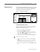
15. Enter the following values for Index 0.
16. Choose
Close to exit the Drive Parameters window.
17. Select
I/O Configuration command icon from the Drive Window.
18. Select an appropriate digital input from the pull-down lists avail-
able as Digital Input Assignments in the I/O Configuration win-
dow.
For example:
•
Start Index as Input 1
•
Registration Sensor as Input 2.
•
Not Assigned as Inputs 3 and 4.
•
Not Assigned as Outputs 1 through 4.
19. Choose
Close to exit the I/O Configuration window.
Tuning
1. Choose the Tuning command icon from the Drive window.
2. Select A
utoTune from the Tuning mode group.
3. Select the appropriate values for the following Auto Tune com-
mands:
•
Distance and
•
Step Current.
4. Select the appropriate entry for the Motor Direction:
•
BiDirectional,
•
Forward Only or
•
Reverse Only.
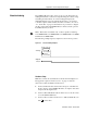
Note: The Registration Distance must be longer than the Deceleration
Distance or the move will not be registered.
Single Move Settings Batched Move Settings
Registration as Mode Registration as Mode
8000 as Distance 8000 as Distance
8000 as Registration Distance
1 as the Batch Count 3 as the Batch Count
0 as Dwell 1000 as Dwell
Appropriate values for Accelera-
tion and Deceleration
Appropriate values for Accelera-
tion and Deceleration
Note: Do not attempt to Auto Tune systems that have gravitational
effects. The ULTRA 200 Series will not hold initial position.