
User Manual

Publication 1398-5.0 – October 1998
7-14 Power Connections
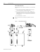
External Shunt Connection
The following procedure outlines the installation of an external shunt
resistor.
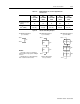
1. Remove jumper between TB1-1 and TB1-2, the internal shunt
connection. The jumper is supplied with the drive.
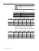
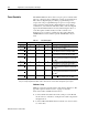
2. Wire an external shunt resistor between TB1-1 and TB1-3, the
external shunt connections. Use wire of the size recommended in
“Minimum Ratings for Customer Supplied External Shunt Resis-
tor” on page 7-13.
3. Torque all terminals to 11.0 lb-in.
Note: A fan may increase the dissipation capability of the shunt
resistor.
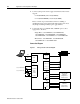
Figure 7.5 External Shunt Mounting Diagram
Intro