
User Manual

Publication 1398-5.0 – October 1998
Chapter 7
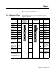
Power Connections Chapter 7
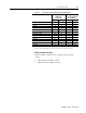
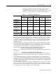
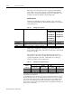
TB1 – DC Bus and AC Power Refer to Figure 5.4 on page 5-11 for power wiring connection
diagrams for the drives.
Description Identifier
1398-DDM-010 and
1398-DDM-010X
1398-DDM-020 and
1398-DDM-020X
1398-DDM-030 and
1398-DDM-030X
Terminal
1398-DDM-075 and
1398-DDM-075X
1398-DDM-150 and
1398-DDM-150X
Identifier Description
R phase power
to motor
R 1 R R phase power
to motor
S phase power
to motor
S 2 S S phase power
to motor
T phase power
to motor
T 3 T T phase power
to motor
Motor case
ground
4 Motor case
ground
DC Bus
+voltage
DC BUS + 5 DC BUS + DC Bus
+ voltage
DC Bus
-voltage
DC BUS - 6 DC BUS - DC Bus
- voltage
100/240 VAC
input power
L1
(Line 1)
7 L1 (Line 1) 100/240 VAC
input power
100/240 VAC
input power
L2
(Line 2)/
N
(Neutral)
8L2
(Line 2)/
N
(Neutral)
100/240 VAC
neutral
Safety (earth)
ground
9 L3 (Line 3) 100/240 VAC
input power for
three phase
1
Auxiliary 100/
240 VAC input
power
L1 AUX 10 Safety (earth)
ground
Auxiliary 100/
240 VAC input
power
L2/N AUX 11 L1 AUX Auxiliary 100/
240 VAC input
power
1
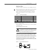
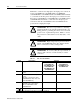
CAUTION: When operating
1398-DDM-075 with a sin-
gle phase power input the
current limits must be set
correctly.
12 L2 AUX Auxiliary 100/
240 VAC
neutral for
three phase