
User Manual


Publication 1398-5.0 – October 1998
6-44 Interfaces
6Interfaces
A1, A2, and COM – Analog
Outputs
Analog outputs may be monitored with external equipment, such as an
oscilloscope, on the external output pins A1 (ANALOG 1), A2
(ANALOG 2) and COM (COMMON). These output signals are
parallel connections to the analog command signals available on
connector J1. Refer to “Analog Outputs” on page 6-16.
A 12-bit digital-to-analog converter (DAC) generates ANALOG 1.
ANALOG 2 is a filtered PWM signal with 8 bit resolution and a
carrier frequency of 32.8 kHz. Both outputs are scaled to a range of
-10 to +10 Volts.
Table 6.16 on page 6-17 lists the output specifications for the signals.
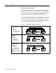
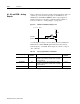
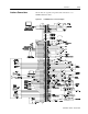
Figure 6.43 ANALOG 1 and ANALOG 2 Output Circuits
Intro
DriveA1 or A2
-5 VDC
10K
100
-
+
20K
ANALOG
OUTPUT
Table 6.26: Analog outputs ANALOG 1 and ANALOG 2
Analog Output Pin
Number
Description Pin
Number
ANALOG 1 A1 Selectable analog output with 12 bit resolution.
Displays any firmware variable with selectable
scale and offset.
J1-30
ANALOG 2 A2 Selectable analog output with 8 bit resolution.
Displays any firmware variable with selectable
scale and offset.
J1-31
COMMON COM Analog Common return. J1-28