
Installation Manual User guide

Publication 1398-5.2 – PDF 1997
Interfaces 6-29
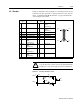
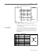
J2 – Encoder Cables are available in various lengths for connecting between J1 and
a suitable controller. Appendix A, “Options and Accessories” lists the
cables. “J2 Terminal Strip/Breakout Board” on page 6-30 details the
optional signal extension kit.
Pin & Sig-
nal
Description Pin & Sig-
nal
Description
1 EPWR Encoder Power 11 I (+) Motor Encoder
Input
Channel I(+)
2 ECOM Encoder Common 12 I (-) Motor Encoder
Input
Channel I(-)
3 EPWR Encoder Power 13 A Hall Effect A
4 ECOM Encoder Common 14 B Hall Effect B
5 EPWR Encoder Power 15 C Hall Effect C
6 ECOM Encoder Common 16 ABS Absolute Position
7 A (+) Motor Encoder
Input
Channel A(+)
17 Reserved
8 A (-) Motor Encoder
Input
Channel A(-)
18 Reserved
9 B (+) Motor Encoder
Input
Channel B(+)
19 TS(+) Thermal Switch (+)
10 B (-) Motor Encoder
Input
Channel B(-)
20 TS(-) Thermal Switch (-)
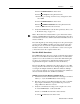
pin 10
pin 11
pin 20
pin 1
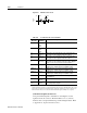
!
Intro
ATTENTION: Ensure that encoder signals are connected
properly. Incorrect connection of encoder signals will result
in improper rotor position and/or incorrect commutation.
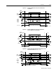
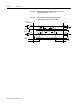
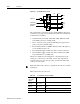
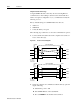
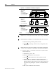
Figure 6.36 Motor Encoder Interface Circuit
-
+
AM26LS33
AM(-)
1K
220pF
AM
220pF
AM(+)
1K
200
.01uF
DriveJ2