
Installation Manual User guide


Publication 1398-5.2 – PDF 1997
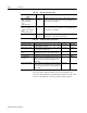
Interfaces 6-23
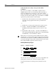
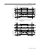
Figure 6.25 External Encoder Interface via TTL Differential Line Drivers
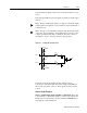
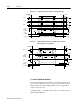
Figure 6.26 Complementary Encoder Interface via 7406 Line Drivers
with Pull-up Resistors
Ch A
ENCODER
AX+
AX-
14
15
J1 Drive
twisted pair
Ch B
BX+
BX-
16
17
twisted pair
Ch I
IX+
IX-
18
19
twisted pair
Drive Chassis
Encoder Case
2
4
+5V
Supply
Return
+5 Volts
1
3
+5V
Supply
+5VDC
5V @ 250 mA
ECOM
twisted pair
For horizontal dashed lines,
connect only if J1 sources Encoder power
ENCODER
J1 Drive
Ch B
BX+
BX-
16
17
twisted pair
Drive Chassis
Encoder Case
+5 Volts
7406
Ch A
AX+
AX-
14
15
+5 Volts
7406
Ch I
IX+
IX-
18
19
+5 Volts
7406
twisted pair
twisted pair
twisted pair
2
4
+5V
Supply
Return
+5 Volts
1
3
+5V
Supply
+5VDC
5V @ 250 mA
ECOM
For horizontal dashed lines,
connect only if J1 sources Encoder power