
Installation Manual User guide


Publication 1398-5.2 – PDF 1997
Interfaces 6-17
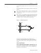
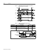
Motor Encoder Output Signal
The motor quadrature encoder signals are supplied to an external
position controller. The signals are differential, quadrature, and TTL
level. The output resolution is selectable and can be divided by 1, 2, 4
or 8.
The signal frequency (f
out
) of the motor encoder output in Hertz (Hz)
can be calculated with the equation:
If the device connected to the motor encoder output counts all edges,
the count frequency is four times f
out
.
For example, a motor with a 2000 line encoder is rotating at 3000 rpm,
and the Motor Encoder Output signal is set to
Divide by 1, the
encoder signal frequency is:
A counter counting all edges registers 400 kHz for this example.
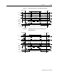
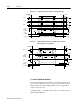
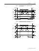
Filter Output Field Voltage Command
R-Phase Current Analog COMMAND Input
T-Phase Current Bus Voltage
Figure 6.21 Output Encoder Interface Circuits
AOUT-
AOUT+
AMOUT
AM26C31 or AM26LS31
DriveJ1
f
out
Vm linecount⋅
60 N⋅
---------------------------------------=
where:
Vm is the motor encoder velocity in rpm
Line count is the number of encoder lines/revolution of
the
motor mounted encoder, and
f
out
3000 2000⋅
60 1⋅
---------------------------- 1 0 0 k H z==