
Installation Manual User guide

Publication 1398-5.2 – PDF 1997
6-16 Interfaces
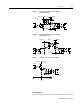
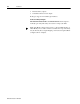
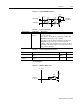
A selectable output is available for monitoring by the user: ANALOG
1 (J1-31).
The following signals can be mapped to the analog output.
The following signals can also be monitored when ULTRA Master is
configured for Advanced Mode.
!
Intro
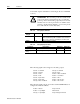
ATTENTION: The user must provide an external circuit
to ignore the analog output signal for two seconds after
power-up. After reset the analog output may be in an inde-
terminate state for a short period before it stabilizes at the
software controlled setting. Failure to observe this precau-
tion could result in severe bodily injury.
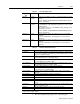
Table 6.15: Analog Outputs: ANALOG 1
Analog
Output
Pin Number Description
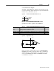
ANALOG 1 J1-31 Selectable analog output. Displays the selected firm-
ware variable along with selectable scale and offset.
The scale or offset are calculated as shown below.
ACOM J1-28 Analog Common (return).
Table 6.16: Analog Output Specifications
Parameter Description Minimum Maximum
Output Current Allowable current draw of the load -2 mA +2 mA
Output Signal
Range
Voltage range of the signal -10 Volts +10 Volts
Current – Command Velocity – Command
Current – Average Velocity – Error
Current – Peak + Position – Motor Feedback
Current – Peak - Position – Command
Current – Input Limit + Position – Error
Current – Input Limit - Position – Error Peak +
Velocity – Motor Feedback Position – Error Peak -
Position – Master Torque Current
Position – Loop Output Field Current
Velocity – Loop Output Torque Voltage Command