
Installation Manual User guide

Publication 1398-5.2 – PDF 1997
Interfaces 6-15
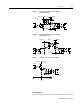
Analog Output
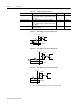
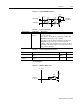
Figure 6.19 Analog COMMAND Input Circuit
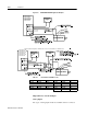
Table 6.13: Analog Command Input
Analog Input Pin Number Description
COMMAND J1-22 (+)
J1-23 (-)
Analog command signal is a differential type signal to drive
the servo controller.
If the drive is in Velocity Mode configuration, the differential
COMMAND signal is the velocity command.
If the drive is in Torque Mode configuration, the differential
COMMAND signal is the torque or current command.
Separate scale and offset parameters are used for the input,
depending on whether the signal is a velocity command or a
torque current command.
Table 6.14: Analog Command Input Specifications
Parameter Description Minimum Maximum
Input Impedance Open circuit impedance measured between (+)
and (-)
13.3
kOhms
Input Signal
Range
Allowable voltage applied between (+) and (-)
inputs
0 Volts ±10 Volts
DriveJ1
COMMAND+
COMMAND-
10K
20K
10K
10K
10K
ANALOG
+
-
COMMAND
10K
10K
.01uF
.01uF
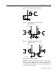
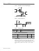
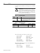
Figure 6.20 ANALOG 1 Output Circuit
DriveJ1
-5 Volts
10K
100
-
+
20K
ANALOG
OUTPUT