
Installation Manual User guide

Publication 1398-5.2 – PDF 1997
6-12 Interfaces
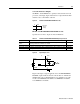
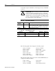
● The command input supports 0 to ±10 Volt signals.
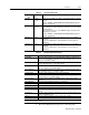
Table 6.10: Transistor Output Specifications
Parameter Description Minimum Maximum
ON state Voltage Voltage difference between the external I/O
power supply and the output when the transis-
tor is ON
0 VDC 1.5 VDC
ON state current Current flow when the transistor is ON 0 mA 50 mA
OFF state Voltage Voltage difference between the external I/O
power supply and the output when the transis-
tor is OFF
0 Volts 50 Volts
OFF state current Leakage current from the output when the
transistor is OFF
-0.1 mA 0.1 mA
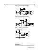
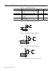
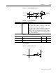
Figure 6.11 Drive Output Connected to an Opto-Isolator
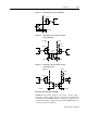
Figure 6.12 Drive Output Connected to an LED Indicator
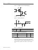
Figure 6.13 Drive Output Connected to a Resistive Load
DriveJ1
I/O Pwr
Pin 13
Pin 6
I/O COM
1K
1K
I/O Pwr
Pin 13
Pin 6
DriveJ1
I/O COM
Pin 13
Pin 6
DriveJ1
I/O COM
I/O Pwr
1K