
Installation Manual User guide

Publication 1398-5.2 – PDF 1997
Interfaces 6-11
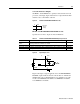
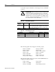
● The current limiting input supports 0 to +10 Volt signals
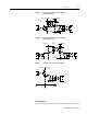
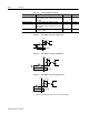
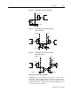
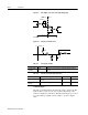
Table 6.8: Selectable Output Circuits
Digital Out-
put
Pin Number Function/Description
READY J1-24 (+)
J1-25 (-)
Relay closure indicates the drive is operational and does
not
have
a fault.
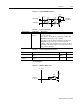
Refer to “READY and BRAKE/DRIVE ENABLED Output Specifi-
cations” on page 6-9
BRAKE J1-49 (+)
J1-50 (-)
Relay closure releases the brake. Delay time is selectable (Refer
to ULTRA Master - I/O configuration) and may be used as a drive
enabled output.
This signal is the inverse of the ENABLE output, although a time
delay may be selected.
Refer to “READY and BRAKE/DRIVE ENABLED Output Specifi-
cations” on page 6-9
OUTPUT 1 J1-42 General purpose output. Selectable from one of several drive
functions.
(Refer to ULTRA Master - I/O configuration on-line Help and
Table 6.9 .)
OUTPUT 2 J1-43 General purpose output. Selectable from one of several drive
functions.
(Refer to ULTRA Master - I/O configuration on-line Help and
Table 6.9 .)
Table 6.9: OUTPUT1 and OUTPUT2 Functions
Function Description
In Position An active state indicates the position window condition is satisfied, and
the zero speed condition is satisfied. The position window and zero speed
range are selectable settings.
Within Window An active state indicates the position window condition is satisfied. The
position window range is a selectable setting.
Zero Speed An active state indicates the velocity loop zero speed signal is active. The
zero speed limit is a selectable setting.
Speed Window An active state indicates the velocity loop speed window is active. The
speed window range is a selectable setting.
Current Limit An active state indicates the torque current is limited.
Up To Speed An active state indicates the velocity loop AT SPEED signal is active. The
at speed level is a selectable setting.
Drive Enabled An active state indicates the ENABLE signal is active and no fault is
detected.
Bus Charged An active state indicates the DC bus is energized.
Disabling Fault An active state indicates a fault disabled the drive.
In Motion An active state indicates the indexing sequence is in the motion portion.
In Dwell An active state indicates the indexing sequence is in the dwell portion.
Sequence Complete An active state indicates all batches of the indexing sequence are fin-
ished.
Registered An active state indicates the indexing move has been adjusted after sens-
ing the registration sensor.
At Home An active state indicates the drive is at the home position.
Axis Homed An active state indicates the drive has been homed.
NOTE: Refer to the I/O Configuration section of the ULTRA Master on-line Help for further expla-
nation of these output signals.