
Installation Manual User guide

Publication 1398-5.2 – PDF 1997
6-10 Interfaces
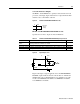
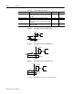
Output Interface Circuit Examples
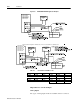
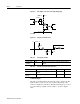
Analog Inputs
Two types of analog input circuits are available on the J1 connector:
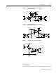
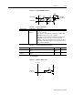
Figure 6.10 BRAKE/DRIVE ENABLE Application Examples
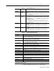
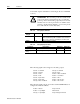
Table 6.7: Current Draw for Brake Motor Coils
MOTOR 24VDC 90VDC MOTOR 24VDC 90VDC
F-4000 0.88A 0.26A Y-1002 0.26A NA
Y-1003 0.26A NA
H-3000 0.60A 0.098A Y-2006 0.31A NA
H-4000 0.69A 0.17A Y-2012 0.31A NA
Y-3023 0.37A NA
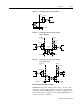
Suggested brake wiring when 24VDC brake current exceeds 500mA or for 90VDC brakes:
1398-DDM-005 and
1398-DDM-005X;
1398-DDM-009 and
1398-DDM-009X;
1398-DDM-019 and
1398-DDM-019X
1398-DDM-005 and
1398-DDM-005X;
1398-DDM-009 and
1398-DDM-009X;
1398-DDM-019 and
1398-DDM-019X