
Installation Manual User guide


Publication 1398-5.2 – PDF 1997
6-4 Interfaces
Refer to the I/O Configuration section of the on-line ULTRA Master
Help for information on choosing the input type for each channel.
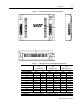
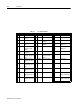
Not Assigned (default) Reverse Enable Start Index
Drive Mode Select Operation Mode Override Define Home
Integrator Inhibit Preset Select A Sensor (available only on INPUT
2)
Follower Enable Preset Select B Remove COMMAND Offset
Forward Enable Preset Select C
Fault Reset Start Homing
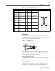
Table 6.2: General and Dedicated Inputs
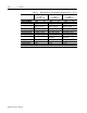
Digital Input Pin Number Function/Description
ENABLE J1-20 Enables and disables the drive. Motor torque cannot be applied
unless the ENABLE input is active.
FAULT RESET J1-21 General purpose input selectable to one of several drive functions.
Refer to ULTRA Master on-line Help and Table 6.3 for I/O configu-
ration.
INPUT 1 J1-32
INPUT 2 J1-33
INPUT 3 J1-34
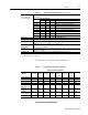
Table 6.3: INPUT1, INPUT2 and INPUT3 Functions
Function Description
Drive Mode Select Active
1
state configures the drive for Torque Mode.
Inactive
2
state selects the personality EEPROM setting as the command source.
Integrator Inhibit Active
1
state zeros the Velocity Loop Error Integrator.
Follower Enable Active
1
state allows the position loop to track the AUXILIARY POSITION LOOP
signal when in the Follower mode.
Forward Enable Active
1
state allows forward commands in velocity mode only. If this input is inac-
tive or not connected, no velocity command will be allowed in the forward direc-
tion. If motion is in progress when the input is pulled low or disconnected, the drive
halts immediately without deceleration control. The COMMAND signal is clamped
internally to 0 Volts.
Reverse Enable Active
1
state allows reverse commands in velocity mode only. If this input is inac-
tive or not connected, no velocity command will be allowed in the reverse direc-
tion. If motion is in progress when the input is pulled low or disconnected, the drive
halts immediately without deceleration control. The COMMAND signal is clamped
internally to 0 Volts.
Operation Mode
Override
Active
1
state selects the Operation Mode Override setting as the command
source.
Inactive
2
state selects the Operation Mode setting as the command source.
Table 6.4 lists the valid Operation Mode and Operation Mode Override combina-
tions.