
Installation Manual User guide


Publication 1398-5.2 – PDF 1997
Interfaces 6-3
Digital Inputs
ULTRA 100 Series drives have active high inputs, which prevent
disconnects and ground faults from activating a drive. The typical ON
time for an input to be recognized is 2.0 msec.
Two discrete input circuits types are available on the J1 connector.
Both circuits support logic type interfaces with optically isolated,
single ended and active high characteristics.
Dedicated Control Circuits
The ENABLE input interface with switch closures or sourcing type
outputs.
Selectable Circuits
INPUT 1, INPUT 2, INPUT 3 and FAULT RESET operate with
switch closures or sourcing type circuitry. Selectable inputs are:
13 I/O COM External I/O
Common
32 INPUT1 Selectable
Input 1
14 AX+/
CW+/
STEP+
Auxiliary
Encoder Chan-
nel A+
33 INPUT2 Selectable
Input 2
15 AX-/CW-/
STEP-
Auxiliary
Encoder Chan-
nel A-
34 INPUT3 Selectable
Input 3
16 BX+/
CCW+/
DIR+
Auxiliary
Encoder Chan-
nel B+
35 Reserved
17 BX-/
CCW-/
DIR-
Auxiliary
Encoder Chan-
nel B-
36 Reserved
18 IX+ Auxiliary
Encoder Chan-
nel I+
37 Reserved
19 IX- Auxiliary
Encoder Chan-
nel I-
38 Reserved
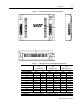
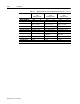
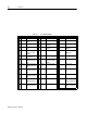
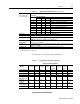
Table 6.1: J1 Controller Pin-Outs (continued)
Pin & Signal Description Pin & Signal Description Pin & Signal Description
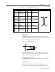
pin 25
pin 26
pin 50
pin 1
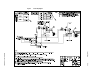
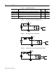
Figure 6.1 Digital Input Circuit
DriveJ1
3K
1K
I/O COM