
Installation Manual User guide

Publication 1398-5.2 – PDF 1997
D-16 Creating Custom Motor Files
Example of Custom Motor
File Creation
The following is an example of a custom motor. A 50:1 gear is
included inside this motor. The example illustrates how to configure a
custom motor.
Manufacturer’s Data
The following specifications were taken from the manufacturer’s data
sheet:
● Reduction Ratio = 1:50
● Rated Current = 1.4 Amp
● Maximum Current = 3.8 Amp
● Maximum Speed = 80 RPM
● Torque Constant = 270 in-lb/Amp
● BEMF = 1.1 Volt/RPM per phase
● Motor Resistance = 3.7Ω
per phase
● Motor Inductance = 5.0mH per phase
● Thermal Time Constant = 30 minutes
● Moment of Inertia = 5.1 in-lb-sec
2
● Encoder Linecount = 1500 lines/rev
● No Integral Thermostat
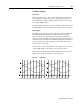
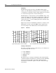
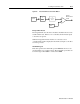
A check with the manufacturer yielded that the motor has 8 poles, and
that the line-to-line back-EMF and Hall signals are as shown in
Figure D.7. The figure indicates that no lead swapping is necessary
but the Hall offset is 120
o
.
Parameter Conversions
The 1:50 gearing makes this motor an unusual case. The motor file
must be generated as if the motor and gear are two separate devices.
The inertia, torque, speed, etc., must be computed based on the motor
side of the gearing, rather than the load side.
The maximum speed of the motor, before gearing, is computed as:
The torque constant of the motor, before gearing, is computed as:
Figure D.7 Back-EMF and Hall Signals, Clockwise Rotation
Intro