
Installation Manual User guide

Publication 1398-5.2 – PDF 1997
8-10 Application and Configuration Examples
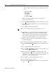
1. Choose the Tuning command icon from the Drive window. The
drive must be configured in Velocity mode for tuning to be effec-
tive.
2. Select
A
utoTune from the Tuning mode group.
3. Select the appropriate values for the following Auto Tune com-
mands:
•
Distance and
•
Step Current.
4. Select the appropriate entry for the Motor Direction:
•B
iDirectional,
•
Forward Only or
•
Reverse Only.
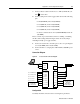
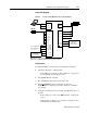
5. Close the toggle switch between J1-26 and J1-20 to enable the
drive.
6. Choose
S
tart from the Tuning window. The drive powers the
motor shaft for a short period and then motion will cease. Then
ULTRA Master displays the calculated gains and disables the
drive.
7. Choose
N
ormal Drive Operation from the Tuning window.
8. Open the switch between J1-26 and J1-20 to disable the drive.
9. Choose
C
lose to exit the Tuning window.
10. Verify the Status indicator is green.
11. Close any open windows or dialog boxes.
Operation
The drive is now configured as a Preset Controller in Velocity or
Torque mode.
● The servo parameters have been setup with the unloaded motor.
● The motor speed or current is controlled through the digital
inputs.
The firmware saves the parameters in EEPROM memory. Thus the
drive can be power cycled and, after power-up, will use the parameters
selected in the steps above.
!
Intro
ATTENTION: Rotating motor shafts can cause extensive
damage and injury. Motors must be properly guarded dur-
ing testing and installation.