
Installation Manual User guide


Publication 1398-5.2 – PDF 1997
8-2 Application and Configuration Examples
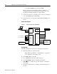
• J1-21 (FAULT RESET) and J1-26 (I/O PWR).
These connections provide manual control for enabling or
disabling the drive and resetting faults. The figure below shows
the jumper, including normally open toggle switches.
6. Connect an external 12 to 24 VDC power source for powering I/O
to J1-5 (I/O PWR) and J1-6 (I/O COM).
7. Connect the drive to a single phase 100-240 VAC, 50/60 Hz power
source.
Connection Diagram
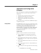
Configuration
Carefully check all connections before entering these parameters.
1. Switch the AC Power to ON and verify:
• Status LED is green. Refer to “Status Indicator” on page 10-1
for an explanation of the display codes.
2. Start ULTRA Master on the PC.
3. Choose
Cancel from the Drive Select dialog box.
4. Select P
C Set Up from the Communications menu in
ULTRA Master to display the personal computer’s communica-
tion settings.
5. Verify the communications port settings of the PC match those of
the drive.
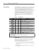
Figure 8.1 Analog Controller Connection Diagram
J1
26 I/O PWR
20 ENABLE
21 FAULT
22 CMND+
23 CMND-
Close to ENABLE Drive
Close to RESET Fault
±10 VDC
DRIVE
L1 3
L2/N 4
Gnd 5
100-240 VAC
50/60 Hz
Single Phase
Power Source
RESET
J5
2 RCV
3 XMT
5 COM
XMT
RCV
COM
TB1
Phase R 6
Phase S 7
Phase T 8
Mtr Gnd 9
J2
Motor
Encoder
External I/O
12-24 VDC
Power Source
5 I/O PWR
6 I/O COM