
Installation Manual User guide


Publication 1398-5.2 – PDF 1997
Chapter 7
Power Connections Chapter 7
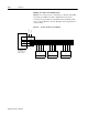
DC bus, single phase AC power and motor connections are provided
on the Terminal Block (TB-1).
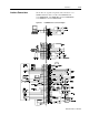
Power Wiring Connection Diagrams for the 1398-DDM-005 and
-005X, 1398-DDM-009 and -009X, 1398-DDM-019 and -019X are
provided in Figure 5.4 on page 5-11. Wiring for the external I/O
power is described and depicted in the chapter “Application and
Configuration Examples” on page 8-1.
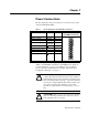
Table 7.1: TB1 - DC Bus and AC Power Terminal Block Connections
Description Identifier Terminal 1398-DDM-005 and -005X
1398-DDM-009 and -009X
1398-DDM-019 and -019X
DC Bus + voltage DC BUS + 1
DC Bus - voltage DC BUS - 2
100-240 VAC input power L1 (Line 1) 3
100-240 VAC input power L2 (Line 2)/
N (Neutral)
4
Safety (earth) ground 5
R phase power to motor R 6
S phase power to motor S 7
T phase power to motor T 8
Motor case ground 9
!
Intro
ATTENTION: DC bus capacitors may retain hazardous
voltages after input power has been removed, but will nor-
mally discharge in several seconds. Before working on the
drive, measure the DC bus voltage to verify it has reached
a safe level or wait the full time interval listed on the warn-
ing on the front of the drive. Failure to observe this
precaution could result in severe bodily injury or loss of
life.
!
Intro
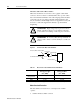
ATTENTION: Motor power connectors are for assembly
purposes only. They should not be connected or discon-
nected while the drive is powered.