
User guide
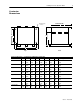
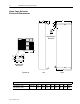
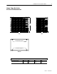

1397 Open Chassis Dynamic Brake
9
1397-5.15 March, 1999
181/L1
81
47 (+)
45 (–)
M
M
A1
M
ARMATURE
SUPPLY
1397 DRIVE
DB RESISTORS
282
281
283
AC
INPUT
82
83
182/L2
182/L3
A1
A2
MOTOR ARMATURE
2
DBR
A2/S1
1
1
1FU
2FU
3FU
3
2
4
F1
F2
1
P6-5
P6-2
RRB1-5RRB1-6
35-F237-F1
DBCR
13
FROM
FIELD
SUPPLY
14
M AUX
DYNAMIC BRAKE
TERMINAL BLOCK
MOTOR SHUNT FIELD
3
S2
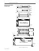
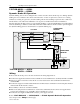
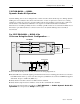
1397-DB-B400L — B600L
Dynamic Brake Kit Operation
Dynamic braking slows down a rotating DC motor and its load. It is an uncontrolled process. During dynamic
braking, the motor armature is disconnected from the drive. A resistor is placed across the motor’s rotating
armature (now acting as a generator), and the resulting current causes braking torque in the motor. The motor
will decelerate, even with a drive malfunction, as long as motor shunt field excitation is maintained.
When the motor is running normally, the drive’s normally-open M contacts are closed and the normally-closed
M contact is open. When the drive is connected to the motor, the dynamic braking resistor assembly is
disconnected.
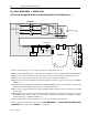
For 1397-DB-B400L — B600L Kits
If You are Using the Basic Configuration . . .
Remove and lockout all power to the drive and follow the wiring diagram above.
➊
Route the DB resistor cables through the grommeted hole in the resistor mounting panel. Connect to connection
bars DBR
&
A2/S1 at the top of the 1397 drive using the (2) M10 hex bolts, washers and KEP nuts supplied
with the kit. Torque to 23.00 N-m (200 lb.-in.).
➋
Verify that the removable connector bar link at A2/S1 is installed.
➌
Verify that the jumper between terminals 3
&
4 at the drive terminal block is installed.
Remove the lockout and reapply power. Refer to
1397-DB-B400L—B600L Dynamic Brake Kit
Operation
above and proceed to
Setup
on the last page.