
User guide

1397 Open Chassis Dynamic Brake14
1397-5.15 March, 1999
181/L1
81
A1 (+)
45 (–)
M
M
A1
M
ARMATURE
SUPPLY
1397 DRIVE
1397 DRIVE
DB RESISTORS
282
281
283
AC
INPUT
82
83
182/L2
182/L3
A1
A2
S2
S1
MOTOR ARMATURE
2
1
5
6
DBR
A2/S1
8
8
1FU
2FU
3FU
3
2
4
F1
F2
1
P6-5
P6-2
RRB1-5RRB1-5
35-F237-F1
DBCR
13
FROM
FIELD
SUPPLY
14
FAN
M AUX
DYNAMIC BRAKE
TERMINAL BLOCK
MOTOR SHUNT FIELD
7
S2
2
A1
S2
DBR
A2/S1
4
3
MOTOR SERIES FIELD
9
10
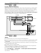
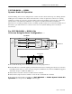
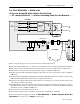
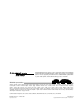
For 1397-DB-B400L — B600L Kits
If You are Using DB with a Motor Series Field
—S1 connected to A2/S1—without an Inverting Fault CIrcuit Breaker . . .
Remove and lockout all power to the drive and follow the wiring diagram above.
➊Follow the wiring diagram above to connect the motor armature to the drive and Inverting Fault Circuit Breaker.
➋Remove the connector bar link at A2/S1, but retain the A2/S1 connection bar and all (4) mounting bolts.
➌Replace the (2) lower bar bolts removed previously. Torque to 23.00 N-m (200 lb.-in.).
➍Replace the upper A2/S1 terminal bar using the (2) upper bar bolts removed previously. Torque to 23.00 N-m
(200 lb.-in.).
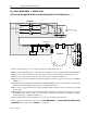
➎Route and connect the A2 motor cable to drive connection bar A2/S1.
➏Route customer supplied cable between A2/S1 and motor connection S1. Cable should be sized to the same
guage as the DB resistor cables.
➐Route and connect the S2 motor cable to drive connection S2.
➑Route the DB resistor cables through the grommeted hole in the resistor mounting panel. Connect to connection
bars DBR
& A2/S1 at the top of the 1397 drive using the (2) M10 hex bolts, washers and KEP nuts supplied
with the kit. Torque to 23.00 N-m (200 lb.-in.).
➒Connect the motor series field between S1 & S2.
➓Verify that the jumper between terminals 3 & 4 at the drive terminal block is installed.
Remove the lockout and reapply power. Refer to 1397-DB-B400L—B600L Dynamic Brake Kit
Operation above and proceed to Setup on the last page.