
Instruction Manual

8 1397 I/O Expansion Card
1397 – 5.19 August, 2000
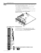
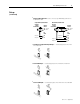
Analog Input Settings
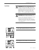
The I/O Expansion Card supports two analog inputs — Anlg In 3
and Anlg In 4.
Anlg In 3 has (4) parameter settings
1
and can be jumpered to accept
(4) types of input signals
3, 4, 5
.
Anlg In 4 has (3) parameter settings
1
and only accepts a bipolar DC
voltage.
Analog inputs can be scaled to use DC voltage signals as low as 4.5V
DC (5V DC ±10%), but the maximum resolution of 0.024% is only
obtained when a full scale input signal is used. Analog inputs are read
every 20mS.
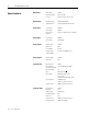
Parameter No. Parameter Name Terminal Nos.
P.003 Anlg In 3 50 and 51
2
P.004 Anlg In 4 52 and 53
2
P.133 Anlg In 3 Type
P.134 Anlg In 3 Zero
P.132 Anlg In 3 Gain
P.136 Anlg In 4 Zero
P.135 Anlg In 4 Gain
1
For a detailed description of these Analog Input Parameters, refer to the parameter descriptions
in the 1397 User manual.
53
54
55
56
57
59
60
61
62
58
J6
J5
38
39
40
41
42
43
44
50
51
52
Anlg In 3
–
Anlg In 4 +
Anlg In 4
–
Anlg In 3 +
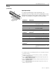
Setup
(continued)
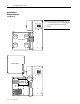
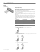
Dig Out 1 Com
Dig Out 2
Dig Out 2 Com
Dig Out 1
66
67
68
69
J9
J8
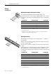
Digital Output Jumper and Parameter Settings
To configure the I/O Expansion Cards digital outputs, only
parameters must be set
1
. The cards (2) digital outputs can be sourced
from various drive functions and will hold their state for a minimum
of 20mS.
Parameter No. Parameter Name Terminal Nos.
P.155 Dig Out 1 SRC 66 and 67
P.157 Dig Out 2 SRC 68 and 69
P.156 Dig Out 1 Type
2
P.158 Dig Out 2 Type
2
1
For a detailed description of these Digital Output Parameters, refer to the parameter descriptions
in the 1397 User manual.
2
If Parameters 156 and/or 158 are configured as normally closed contacts, they will act as
normally open contacts during a drive power cycle.