
Instruction Manual

6 1397 I/O Expansion Card
1397 – 5.19 August, 2000
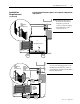
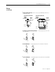
Setup
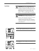
Depending upon the application, jumpers as well as parameters are
used to configure the I/O Expansion Card.
• 1 to 4 jumpers on the card may have to be changed from their
factory settings to accommodate I/O signals.
• (19) input and (8) output parameters are dedicated to program the
card’s I/O signals.
For a detailed description of I/O Expansion parameters, refer to the
parameter descriptions in the 1397 User Manual
(Publication 1397-5.0).
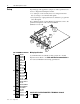
Jumper
J15
J14
Jumpers
I/O
Terminal
Block
J5
I/O
Terminal
Block
J6
I/O
Terminal
Block
J7
I/O
Terminal
Block
J9
I/O
Terminal
Block
J8
J11
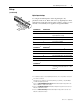
10-50
ANALOG
OUTPUT 1
IOUT
SOURCE
INT EXT
J15
J12
4-20
PARK
VOLTS
V
M
A
(ANALOG INPUT 1)
J5
J6
J2
J1
J10
33
34
38
39
40
41
42
43
44
50
51
52
53
54
55
56
57
58
59
60
61
62
63
64
65
66
67
68
69
J14
M
A
V
J11
Jumpers
Jumper
J12
Aux Pot
Terminal
Block
J10
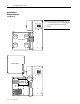
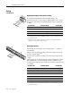
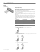
Wiring Specifications
(5) terminal blocks are available for I/O connections to the I/O
Expansion Card. Refer to the Cable and Wire Recommendations in
the 1397 User Manual for I/O wiring specifications
62
38
39
40
41
42
43
44
50
51
52
53
54
55
56
57
58
59
60
61
UNUSED
FREQ IN A
FREQ IN A
COM
COM
ANLG IN 3 –
ANLG IN 4 +
ANLG IN 4 –
ANLG OUT 3 +
ANLG OUT 3 –
ANLG OUT 4 +
ANLG OUT 4 –
+24V DC
PRESET SPEED B
PRESET SPEED A
+24V DC
MOP DECREMENT
ANLG IN 3 +
FREQ OUT A
FREQ OUT A
63
64
65
MOP INCREMENT
OCL ENABLE
24V COM
66
67
DIG OUT 1
DIG OUT 1 COM
68
69
DIG OUT 2
DIG OUT 2 COM
J5
I/O TERMINAL BLOCK
J6
J7
J8
J9
AUXILIARY POTENTIOMETER TERMINAL BLOCK
33
34
10V DC
GND
J10