
Instruction Manual

4–22 Start–Up and Adjustment
Publication 1397-5.0 — June, 2001
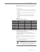
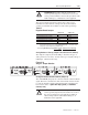
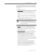
Figure 4.9
Regulator Board Jumpers
J7
J17
ARM
1
J24
J23
J25
J22
GROUND
ARM 1
FB RB
J18
J6
J28
J26
803624-093A
A
B 1397
J2
J1
J5
1
2
3
4
5
6
7
8
9
10
11
12
13
14
15
16
17
18
19
20
21
22
23
24
25
26
27
28
29
30
31
32
M
A
N
U
A
L
R
E
F
J19
E
X
T
P
O
T
T
A
C
H
V
R
A
N
G
E
J14
H
I
2
5
0
m
a
x
L
O
6
2
m
a
x
V
O
L
T
S
M
A
M
P
S
A
U
T
O
R
E
F
J12
S
P
E
E
D
C
U
R
R
E
N
T
R
E
G
U
L
A
T
O
R
T
Y
P
E
J15
E
N
A
B
L
E
F
IE
L
D
L
O
S
S
D
E
T
E
C
T
J20
D
IS
A
B
L
E
J16
O
IM
P
R
O
G
R
A
M
E
N
A
B
L
E
D
IS
A
B
L
E
J21
F
IE
L
D
S
U
P
P
L
Y
J
U
M
P
E
R
B
-C
A
-
C
T
A
C
H
V
S
C
A
L
E
J11
6
2
/2
5
0
3
1
/1
2
5
1
6
P
A
R
K
10-50
(BO
TH)
J10
A
U
T
O
R
E
F
V
O
L
T
S
4
-
2
0
J3
J4
J27
J10
J14
J11
J19
J18
J20
J15
J21
J16
J12
Setting Field Loss Detection (Jumper J20)
The Field Loss Detect jumper (J20) determines whether or not a fault
is generated when a field loss occurs.
IMPORTANT: Jumper J20 is ignored if the Field Current Regulator
kit is installed. Therefore, placing J20 in the Disable position will
not disable field loss detection. See the instructions supplied with
the kit for more information on the Field Current Regulator.
NOTE: Jumper J20 has no effect if the drive is equipped with an
enhanced or regulated field supply.