
Instruction Manual

4–11Start–Up and Adjustment
Publication 1397-5.0 — June, 2001
Pre-Power Verification
!
ATTENTION: Prior to energizing the Drive, it is
imperative that the installation instructions in Chapter 2
and the Pre-Power checks listed in the previous section
be completely accomplished. No attempt to apply
power should be made if the installation is in question.
Failure to properly install and configure the Drive or
options could result in personal injury and/or
equipment damage.
Additionally, you must verify that all Drive options are properly
configured for their intended application. These options include, but
are not limited to:
OPTION INSTALLATION MANUAL
• Enhanced Field Supply 1397 – 5.24
• Regulated Field Supply 1397 – 5.17
• 60 HP AC Line Disconnect 1397 – 5.11
• Dynamic Braking 1397 – 5.14
• Pulse Encoder Interface 1397 – 5.13
• Expansion I/O 1397 – 5.19
• AC Tach Interface 1397 – 5.22
• 460/230V Fuse Kit 1397 – 5.16
• Blower Motor Starter 1397 – 5.20
• 150 HP AC Line Disconnect 1397 – 5.21
• 115VAC Control Int Bd 1397 – 5.18
• Inverting Fault C.B. Kit 1397 – 5.29
• AC Line Disconnect Kit 1397 – 5.30
• AC Line Filter Kit 1397 – 5.31
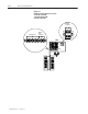
Ensure that the Coast/Stop input between terminals TB-7 and TB-8
of the Regulator Board is locked in the open state.
If the Drive is equipped with an optional AC disconnect, verify that
the disconnect is in the open position.
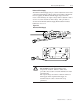
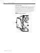
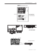
Record the motor field polarity in Table 4.B, as terminated at
terminals F1 and F2 of the field terminal strip (Figures 4.7 & 4.8).