
Instruction Manual

2–34 Installation
Publication 1397-5.0 — June, 2001
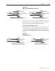
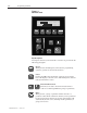
TB–11 POWER – A 24VDC supply is available at this pin.
TB–12 MOTOR BRUSH WEAR – Level sensitive input that
causes a motor brush wear alarm (0 = ALARM). The
Drive can still operate under this condition. This input
CANNOT be masked.
TB–13 MOTOR THERMOSTAT – Level sensitive input that
causes a motor thermostat fault (0 = FAULT). The
Drive will be faulted while this input is true. This input
CANNOT be masked.
TB–14 POWER – A 24VDC supply is available at this pin.
TB–15 COMMON – A 24VDC common supply is available at
this pin.
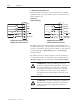
TB–16,17,18 ANALOG REFERENCE 2 – Fixed ± 10VDC analog
reference.
TB–19,20 ANALOG REFERENCE 1 – Signal type selected by
Anlg In 1 Type (P.128) parameter (0–10 VDC, ±10
VDC, 4-20mA, 10–50mA) and hardware jumpers on
the regulator board (J10 and J12).
TB–21,22,23 ANALOG TACHOMETER IN – Use of #21 or #22 is
determined by J14 hardware jumper on the regulator.
ATTENTION: If motor rotation is changed by
reversing either the motor armature lead connections or
the field connections, the Pulse Encoder feedback
polarity on the B and NOT B leads must be reversed. If
a DC Tach is used, feedback polarity must also be
reversed. Failure to observe this precaution could result
in personal injury or damage to equipment.
!
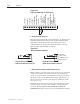
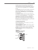
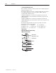
1. Wiring the Coast Stop Circuit
The 1397 Drive has the capability to accept an input from either a
24VDC or 115VAC contact (If the 115 VAC Control Option Board is
installed). The contact must be normally closed and will typically be
a Stop pushbutton. Refer to the following paragraphs for connection
information. This input cannot be masked and is always active.
ATTENTION: The Run/Stop and customer interlock
circuitry in this Drive is composed of solid-state
components. A hardwired Coast to Stop circuit must be
used with this Drive. For 115VAC control, this
circuitry may be added on the optional 115VAC Control
Board.
!