
Instruction Manual

Using SCANport CapabilitiesD–6
Publication 1397-5.0 — June, 2001
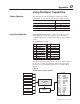
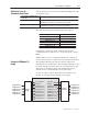
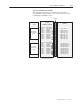
Within the 1397 Drive, the I/O image table resembles the following:
Logic Command Logic Status
(parameter 190)
Bit 0 Stop Bit 0 Ready
Bit 1 Run Bit 1 Running
Bit 2 Jog Bit 2 Command Dir
Bit 3 Clear Fault Bit 3 Rotating Dir
Bit 4 Forward Bit 4 Accelerating
Bit 5 Reverse Bit 5 Decelerating
Bit 6 Local Bit 6 Warning
Bit 7 MOP Increment Bit 7 Faulted
Bit 8 N A Bit 8 At Set Speed
Bit 9 N A Bit 9 Local ID
Bit 10 N A Bit 10 Local ID
Bit 11 N A Bit 11 Local ID
Bit 12 Ref Select Bit 12 Ref ID
Bit 13 Ref Select Bit 13 Ref ID
Bit 14 Ref Select Bit 14 Ref ID
Bit 15 MOP Decrement Bit 15 Ref ID
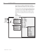
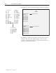
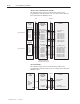
1397
Controller
Logic Evaluation Block Logic Status (p. 190)
Reference
Data In A1 (p. 226)
Data In A2 (p. 227)
Data In B1 (p. 228)
Data In B2 (p. 229)
Data In C1 (p. 230)
Data In C2 (p. 231)
Data In D1 (p. 232)
Data In D2 (p. 233)
Logic Status (p. 190)
Feedback Spd Loop Fdbk (p. 22)
Data Out A1 (p. 234)
Data Out A2 (p. 235)
Data Out B1 (p. 236)
Data Out B2 (p. 237)
Data Out C1 (p. 238)
Data Out C2 (p. 239)
Data Out D1 (p. 240)
Data Out D2 (p. 241)
000 – No Command
001 – Ref 1 (Selectable)
010 – Ref 2 (Selectable)
011 – Ref 3 (Preset 1)
100 – Ref 4 (Preset 2)
101 – Ref 5 (Preset 3)
110 – N/A
111 – N/A
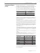
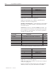
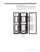
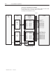
The following examples are provided to show how the 1397 Drive
interfaces with some of the available adapters. These are only
examples. You should also refer to the appropriate manual for your
gateway for additional information.