
Instruction Manual

Using SCANport CapabilitiesD–2
Publication 1397-5.0 — June, 2001
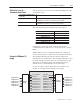
You can attach any combination of Human Interface Modules
(HIMs), Graphic Programming Terminals (GPTs), and/or SCANport
gateway communications modules to any of the six SCANports.
You can access ports 1 and 2 directly from the regulator board. To
access ports 3, 4, and 5, you need to plug a Port Expander into port
2. Normally, port 1 is connected to a HIM. The terminal block is
always present. On the 1397 Drive, there is no direct access to
Port 6. However an adapter identified as 6 will still be scanned.
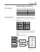
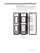
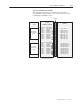
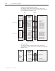
Figure D.2 shows the parameter interactions involved with Logic
Status.
Figure D.2
Parameter Interactions
SCANport 1
Logic Status
(Parameter 190)
SCANport 2
SCANport 3
SCANport 4
SCANport 5
SCANport 6
Terminal Board
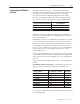
0000 – Ext Ref 1
0001 – Preset 1
0010 – Preset 2
0011 – Preset 3
0100 – N/A
0101 – N/A
0110 – N/A
0111 – N/A
1000 – Ext ref 2
1001 – Port 1 ref
1010 – Port 2 ref
1011 – Port 3 ref
1100 – Port 4 ref
1101 – Port 5 ref
1110 – Port 6 ref
1111 – Int Jog ref
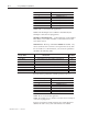
Bit 0
Bit 1
Bit 2
Bit 3
Bit 4
Bit 5
Bit 6
Bit 7
Bit 8
Bit 9
Bit 10
Bit 11
Bit 12
Bit 13
Bit 14
Bit 15
Ready
Running
Command Dir
Actual Dir
Accelerating
Decelerating
Alarm
Fault
At Speed
Local ID
Local ID
Local ID
Ref ID
Ref ID
Ref ID
Ref ID
Logic Mask (P. 207)
Run Mask (P.201)
Jog Mask (P. 203)
Flt/Res Mask (P. 205)
Reference Mask (P. 204)
MOP Mask (P. 206)
Local Mode (P. 208)
Direction Mask (P. 202)
Stop Owner (P. 214)
Run Owner (P. 215)
Direction Owner (P. 205)
Jog Owner (P. 204)
Reference Owner (P. 206)
Flt Reset Owner (P. 208)
MOP Owner (P. 202)
Local Owner (P.221)