
Instruction Manual

6–4 Troubleshooting
Publication 1397-5.0 — June, 2001
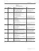
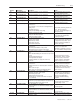
Fault No. Fault Name Description Action
008 “Motor Over Temp” The motor thermostat is indicating a high temperature, or
if no motor thermostat is installed, the customer terminal
board pins 13 and 14 have not been jumpered correctly to
inhibit this fault:
Other possible causes Include:
• Damaged thermostat or disconnected wiring
• Inadequate ventilation
• Blower Motor Malfunction
• Incorrect blower rotation
• Blocked ventilation slots
• Clogged filters
• Excessive armature current
• One or more thyristors inoperable
Check filters, blowers and thermostat,
repairing or replacing as necessary.
Replace thyristors if necessary.
Check motor ventilation and provide
additional air movement or cooling if
necessary.
009 “Cntlr Over Temp” The Controller thermostat is indicating an overtemperature
condition possibly due to:
• Inadequate heat sink ventilation
• Inadequate cabinet ventilation
• Heat sink fan malfunction
• Damaged, disconnected or improperly connected
thermostat wiring
Check the fan and thermostat
repairing or replacing as necessary.
Check cabinet & heat sink ventilation
and provide additional air movement
or cooling as required.
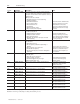
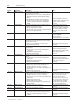
010 “AC Line Sync Flt” Three–phase AC line synchronization circuit malfunction
possibly due to:
• Blown AC line fuses (s)
• AC line frequency outside the required range of
48–62Hz
• Excessive AC line noise or distortion
• Unstable AC line frequency
• Disconnected, improperly connected or damaged J6
ribbon cable
Check all cables and connections.
Replace blown line fuses if necessary.
Line filters or a transformer may be
necessary to cure line frequency or
noise problems.
011 “Arm Over Voltage” Armature voltage exceeded 130% of Motor Arm Volts
(Par 046) due to:
• Motor Arm Volts not set properly
• Improper voltage loop tuning
• [E–Fld Volts Adj] (Par 272) set too high
(Enhanced Field Supply only).
Reset Parameters 44 and 272 if
necessary. Rerun Voltage Loop
Tuning if required.
012 “CAN Comm Lost” Drive to Drive or Drive to Control communication lost. Check attached communication
peripherals for proper operation.
Replace if necessary.
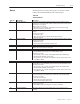
015 “SCR #1 Open Flt” Indicates SCR number 1 is non–operational Check SCR wiring and connections
and replace SCR if necessary
016 “SCR #2 Open Flt” Indicates SCR number 2 is non–operational Check SCR wiring and connections
and replace SCR if necessary
017 “SCR #3 Open Flt” Indicates SCR number 3 is non–operational Check SCR wiring and connections
and replace SCR if necessary
018 “SCR #4 Open Flt” Indicates SCR number 4 is non–operational Check SCR wiring and connections
and replace SCR if necessary
019 “SCR #5 Open Flt” Indicates SCR number 5 is non–operational Check SCR wiring and connections
and replace SCR if necessary
020 “SCR #6 Open Flt” Indicates SCR number 6 is non–operational Check SCR wiring and connections
and replace SCR if necessary
021 “SCR #11 Open Flt” Indicates SCR number 11 is non–operational Check SCR wiring and connections
and replace SCR if necessary
022 “SCR #12 Open Flt” Indicates SCR number 12 is non–operational Check SCR wiring and connections
and replace SCR if necessary
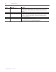
NOTE: Incorrect setting of [CT TURNS RATIO] (P. 036) can also cause faults 015 thru 027. Set the correct value in
Parameter 36 and repeat the jumper setting and autotune process.