
Instruction Manual

5–92 Programming Parameters
Publication 1397-5.0 — June, 2001
Process PI
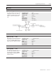
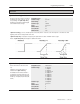
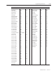
[OCL LeadLag Ratio] — P.292
The ratio between the low break frequency
and high break frequency of outer control
loop lead/lag. The settings of this parameter
and the [OCL LeadLag Freq] determine the
high break frequency.
Refer to the [OCL LeadLag Freq] parameter
and block diagram for additional information.
Display/Drive Units: Numeric/Text
Parameter Range: 2 to 20
Default Setting: 10
Parameter Type: Tunable
Group: Process PI
Minimum Value: 2
Factory Default: 10
Maximum Value 20
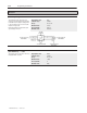
[OCL LeadLag Type] — P.293
Selects the outer control loop as lead/lag,
lag/lead, or bypassed.
If the OCL is configured as a type 1 position
regulator, this should be set to Bypass. For a
type 2 position regulator, the lead/lag block
can be used if necessary
Refer to the [OCL Lead/Lag Freq] parameter
and block diagram for additional information.
Display/Drive Units: Numeric/Text
Parameter Range: 0 = Lead/Lag
1 = Bypass
2 = Lag/Lead
Parameter Type: Tunable
Group: Process PI
Minimum Value: 0
Factory Default: 1
Maximum Value 2
[OCL Kp] — P.294
The proportional gain of the outer control loop
PI block. Refer to the [OCL Lead Freq] block
diagram for additional information.
Display/Drive Units:
Parameter Type: Tunable
Group: Process PI
Minimum Value: 0.10
Factory Default: 2.0
Maximum Value 128.00