
Instruction Manual


5–56 Programming Parameters
Publication 1397-5.0 — June, 2001
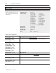
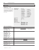
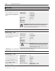
OUTPUT CONFIG
[Anlg Out 3 Src] — P.151
Only used if the I/O Expansion kit is installed.
Selects the signal used to drive analog output
3 (terminals 54 and 55 on the I/O Expansion
board). When the analog output is at its
maximum value, the selected signal is at its
full scale value.
Display/Drive Units: Numeric/Text
Parameter Range: 0 = Cur Lp Fdbk 11 = Arm Volt
1 = Cur Loop Ref 12 = ATach Fdbk
2 = Cur Loop Err 13 = Encoder Fdbk
3 = Spd Loop Fdbk 14 = Zero
4 = Spd Lp Ref 15 = Full Scale
5 = Spd Lp Error 16 = Power Output
6 = Spd Lp Out 17 = OCL Ref
7 = Spd Ramp Out 18 = OCL Ramp Out
8 = Spd Ramp In 19 = OCL Feedback
9 = Spd Src Out 20 = OCL Output
10 = Trim Output 21 = Field Ref
22 = Field Fdbk
See Table A below for Full Scale Values
Parameter Type: Configurable
Group: Output Config
Factory Default: 0
Minimum Value: 0
Maximum Value: 22
Refer also to Parameters: [Maximum Current] — P.040
[Motor Field Amps] — P.044
[Motor Arm Amps] — P.045
[Motor Arm Volts] — P.046
[Max Motor Speed] — P.041
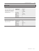
Table A – Source Signal Values
Signal Selected Full Scale Value
[Cur Loop Fdbk] — P.006
[Cur Loop Ref] — P.008
[Cur Loop Error] — P.007
[Spd Loop Output] — P.024
[Motor Arm Amps (P. 45)] × Maximum Current (P. 40)
100 = Full Scale Value
[Spd Loop Fdbk] — P.022
[Spd Loop Ref] — P.025
[Spd Loop Error] — P.021
[Spd Ramp Output] — P.028
[Spd Ramp In TP] — P.027
[Spd Src Output] — P.026
[Trim Output] — P.030
[Analog Tach Fdbk] — P.194
[Encoder Fdbk] — P.189
[OCL Output] — P.018
Top Speed
[Armature Voltage] — P.005 [Motor Arm Volts]
Power Output
[Motor Arm Volts] × [Motor Arm Amps] × Maximum Current
100
[Fld Reference] — P.280
[Field Feedback] — P.010
[Motor Field Amps]
[OCL Reference TP] — P.020
[OCL Ramp Output] — P.019
[OCL Feedback] — P.017
4095