
Instruction Manual

1–7Introduction
Publication 1397-5.0 — June, 2001
The following sections describe drive inputs and outputs. Refer to
Chapter 3 for terminal strip connections and wiring diagrams.
Logic Inputs
!
ATTENTION: Connecting an external power source
to any of the +24 volt connections (terminals 1, 7, 11,
and 14) on the regulator board terminal strip will
damage the drive. Do not connect the external power
source to the +24 volt connections on the regulator
board terminal strip. Failure to observe this precaution
could result in damage to, or destruction of, the
equipment.
The logic input circuits can be powered either from the internal +24
VDC power supply or from an external +24 VDC power source. The
internal +24 VDC power supply is available at the regulator board
terminal strip (see Fig. 2.15). If an external power source is used,
only its common must be connected to 24VCOM on the regulator
board (terminal 15).
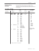
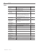
Electrical Specifications
Input Voltage +24 VDC
Turn On Voltage +8 VDC
Turn Off Current 0.5 mA
Common All input circuits have the same
common.
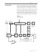
The logic output circuits are normally open (when de-energized)
relay contacts. When energized (contacts closed), the three circuits
indicate the following drive conditions. Terminals are on the
terminal strip on the regulator board.
Running Terminal 27 to 28
Alarm Terminal 29 to 30
No Fault Terminal 31 to 32
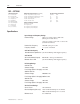
Electrical Specifications
Operating Voltage 250 VAC maximum
30 VDC maximum
Switching Current 2 Amps maximum resistive
1 Amp maximum inductive
Drive I/O Specifications
Logic Inputs
Logic Outputs