
Instruction Manual

4–29Start–Up and Adjustment
Publication 1397-5.0 — June, 2001
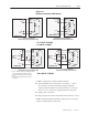
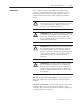
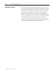
NOTE: If the DC motor used for this application doesn’t
possess a brush wear indicator, verify that terminals 12 and 14 of
the regulator board terminal strip are jumpered (Figure 4.12).
Regulator Board Terminal Strip
24VDC Brush Wear Circuit
12
13
14
BRUSH WEAR
MOTOR THERMOSTAT
+24V
Jumper here for
non–wear indicator
use
Figure 4.12
Brush Wear Option
7. Other Standard Inputs
– Other I/O may or may not be wired to
the Drive, depending on the application. The Drive may be
operated through the Human Interface Module (HIM) without
connecting the remaining I/O. Other inputs may be verified as
described in the preceding steps.
NOTE: If the Drive will be operated using a SCANport device
such as the Bulletin 1203-GD1/GK1, 1203-GD2/GK2,
1203-GK5, 1203-FB1 & FM1, or 1203 SM1 additional set–up
is required. See the chapter entitled Programming Parameters
and the installation manual of the specific SCANport device.
!
ATTENTION: Prior to running polarity checks, you
must provide a hard wired maintained external operator
accessible coast/stop pushbutton at regulator board
terminals 7 and 8 to disable the machine in case of
improper operation. Uncontrolled machine operation
can result if this is not done. Failure to observe this
precaution could result in severe bodily injury or loss
of life.
Motor and Feedback
Polarity Checks