
Owner's manual


1397 Blower Motor Starter
6
1397-5.20 April, 1998
REMOVE
DON'T REMOVE
R MOTOR
STARTER KITS
283
5FU4FU
282
281
183
182
181
Man|Aut
16
A
18
13
15
6
4
2
R
R
0
95969798
T1
T2
T3
5-
13
2
-
2
T1
3
-
4
T2
4
-
6
T3
5-
14
REPLACE WITH
LITTLEFUSE, TYPE CCMR, 600V 2.5A
13FU
14FU 15FU
2-
1
L1
3
-
3
L2
4
-
5
L3
P8
P8
L2
L1
288 289
3
3
4b
1
2
2
4a
4c
4c
Man|Aut
16
A
18
13
15
6
4
2
R
R
0
95969798
T1
T2
T3
5-
13
2
-
2
T1
3
-
4
T2
4
-
6
T3
5-
14
REPLACE WITH
LITTLEFUSE, TYPE CCMR, 600V 2.5A
13FU
14FU 15FU
2-
1
L1
3
-
3
L2
4
-
5
L3
OFF
R MOTOR
STARTER KITS
283
81 82 83
5FU4FU
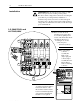
!
DANGER
RISK OF ELECTRICAL SHOCK. DISCONNECT INPUT
POWER BEFORE SERVICING EQUIPMENT.
P/N 33145
282281
288 289
181/L1
182/L2
183/L3
L3
400-600HP/460V
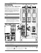
Drive Installation
Single Blower Motor Applications
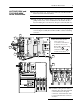
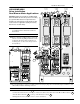
❐
2
Remove and lock-out all incoming power to the
drive. Loosen the (2) phillips head screws on the
molded fuse block and slide the kit’s keyed
mounting slots over the screws — the kit may
be mounted at either location on the fuse block.
Torque to 6.22 N-m (55 lb-in.).
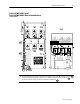
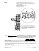
❐
4
Loosen the harness fastener screw .
Connect and route the leads of the long 3-conductor wire harness from the bottom of the Blower Motor Starter
under the harness fastener to the top of the line fuses as shown .
Hand tighten the harness fastener screw to secure the harness.
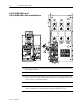
❐
3
Locate one of the P8 jumper connector assemblies. Remove the jumper plug and connect jumper assembly P8 to the
Blower Motor Starter’s matching connector. For single Blower Motor Starter applications, leave the other P8 jumper
connector assembly alone.
❐
1
Disconnect wires 181, 182 & 183 from the back
of the Blower Motor Starter fuse block and discard
them.
Important:
Each blower motor requires it’s own Blower Motor
Starter. 400-600HP 1397 drives have provisions for mounting
up to (2) Blower Motor Starters. For single blower motor
applications, the starter kit may be mounted at either location
on the fuse block. For applications requiring more than (2)
blower motors, consult the factory.
4b
4b
4a
4c