
Owner's manual


1397 Blower Motor Starter2
1397-5.20 April, 1998
Man|Aut
16
A
18
13
15
6
4
2
R
R
0
95969798
T1
T2
T3
5-
13
2
-
2
T1
3
-
4
T2
4
-
6
T3
5-
14
REPLACE WITH
LITTLEFUSDE, TYPE CCMR, 600V 2.5A
13FU
14FU 15FU
2-
1
L1
3
-
3
L2
4
-
5
L3
183/L3
Man|Aut
16
A
18
13
15
6
4
2
R
R
0
95969798
T1
T2
T3
5-
13
2
-
2
T1
3
-
4
T2
4
-
6
T3
5-
14
REPLACE WITH
LITTLEFUSE, TYPE CCMR, 600V 2.5A
13FU
14FU 15FU
2-
1
L1
3
-
3
L2
4
-
5
L3
P8
L3
L2
L1
181/L1
182/L2
1
2
REMOVE
1
3
81 82
83
❐
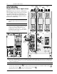
1
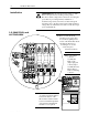
Remove and lockout all
incoming power to the drive.
Loosen the (2) phillips head
screws on the molded fuse block
and slide the kit’s keyed
mounting slots over the
screws. Torque to
6.22 N-m (55 lb-in).
Installation
ATTENTION:
Electric Shock can cause injury or death.
Remove all power before working on this product.
The drive is at line voltage when connected to incoming AC
power. Before proceeding with any installation or
troubleshooting activity, disconnect, lockout and tag all
incoming power to the drive. Verify with a voltmeter than no
voltage exists at terminals L1, L2 and L3 on the drive input
power terminal block.
!
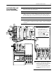
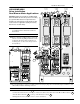
1.5-30HP/230V and
40-75HP/460V
❐
2
Locate jumper
connector
assembly P8.
Remove the
jumper plug and
connect jumper
assembly P8 to the
Blower Motor
Starter’s matching
connector.
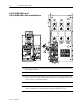
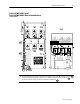
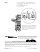
❐
3
Connect the leads of the short
3-conductor spade wire harness
between the bottom of the
Blower Motor Starter and the
bottom of an AC line input fuse
as shown. The remaining kit
hardware is not required.