
Instruction Manual


1397 600HP AC Line Disconnect
4
1397-5.30 July, 1998
BLOWER MOTOR
STARTER KITS
283
5FU4FU
282281
288 289
ON
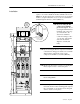
M8 Bolt
and Lock-
washer
M8 Bolt
and Lock-
washer
Cover
Screw
Cover
Screw
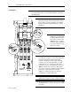
7/16" Flat Washer
7/16" Split Lockwasher
7/16" x 1" Bolt
— (6) Places —
Bus Bar
(top)
M12 Nuts
— (6) Places —
Bus Bar
(bottom)
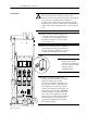
Adapter
M5 × 20
mm Screw
and M5 Toothed
Lockwasher
Installation
❐
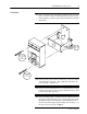
9
While holding the spacer and adapter plate in place, pick up the
disconnect and position it over the threaded holes on the drive’s
mounting panel.
❐
11
Install the M5
×
20mm
phillips head screw and M5
toothed lockwasher where
the screw was removed in
Step 4
. Torque to 2.8 N-m
(25 lb-in.). This establishes
a ground connection for the
disconnect switch.
❐
13
Replace the disconnect’s bottom lug cover and
tighten the (2) captive screws to secure it in place.
❐
14
Replace the plastic line fuse cover removed in
Step
1
and tighten the (2) screws at the bottom to secure
it in place.
❐
12
Remove the disconnect’s lower lug cover by
loosening the (2) captive cover screws. Attach a bus
bar between the drive’s right-side line fuse
connector and the disconnect’s right-side load
connector. Use (2) 7/16" flat washers, (2) split
lockwashers
&
(2) 1" bolts for the disconnect
connection. Use two of the M12 nuts removed in
Step 3
for the line fuse connection. Repeat this
procedure to attach the remaining bus bars. Tighten
the bus bar to disconnect bolts to 34N-m
(300lb.-in.). Tighten the bus bar to line fuse
terminal nuts to 24 Nm (210 in-lb).
❐
10
Attach the disconnect by hand tightening the (2) bolts
inserted previously. After the bolt threads catch in
the bolt holes, insert the remaining (2) mounting
bolts
&
lockwashers. Tighten all bolts to 14N-m
(125lb.-in.).